| Comet "Stick" Models In CAD Format | |
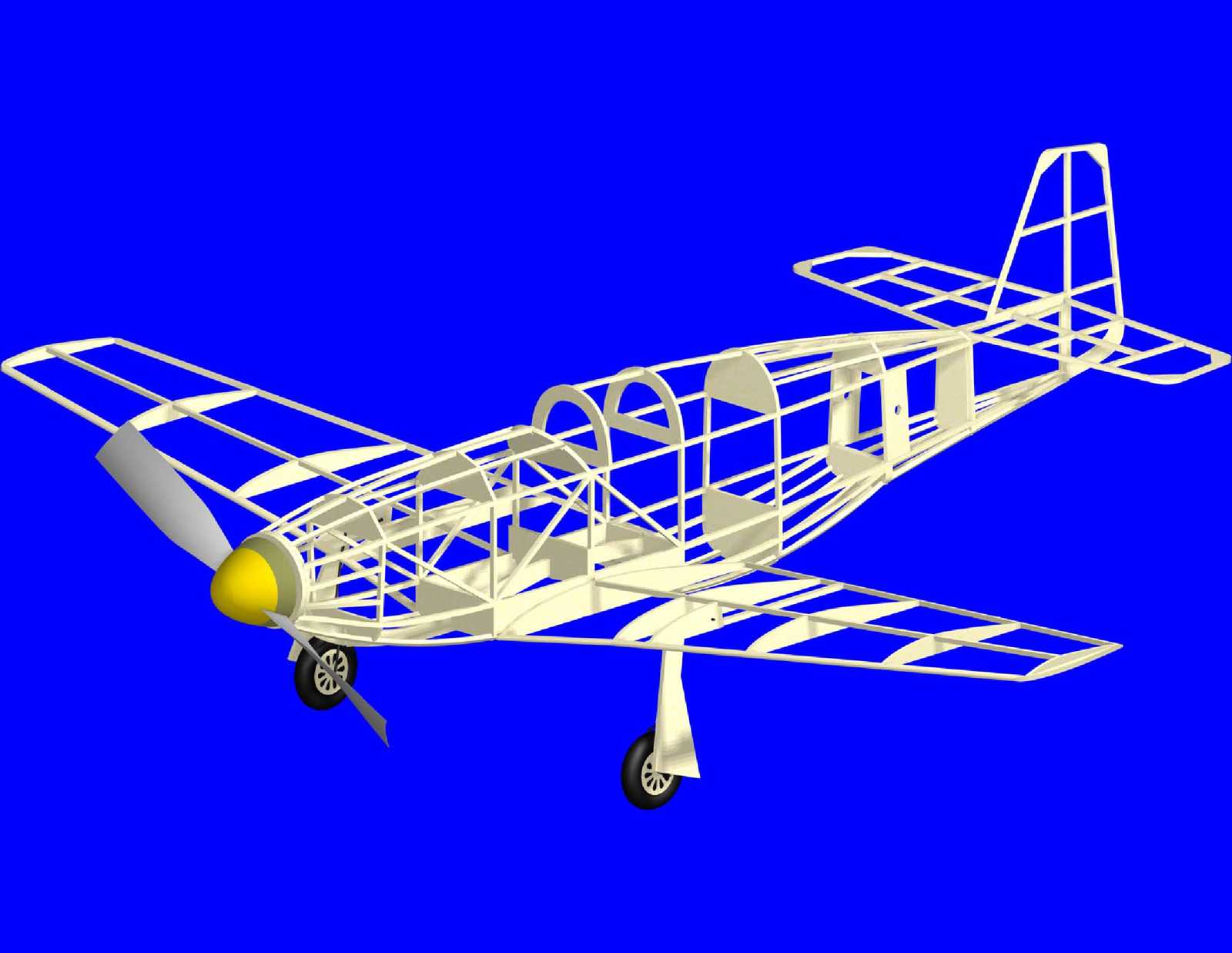   |
Comet P-51. One of the most prolific companies for developing varied
model airplane designs and kits was Comet Models. They began designing
and selling model airplane kits in the '30's and continued for much of
that century before ceasing operations. During the life of the company
they developed more designs than most people can catalog. I have always
had a soft spot for the Comet "stick" models.
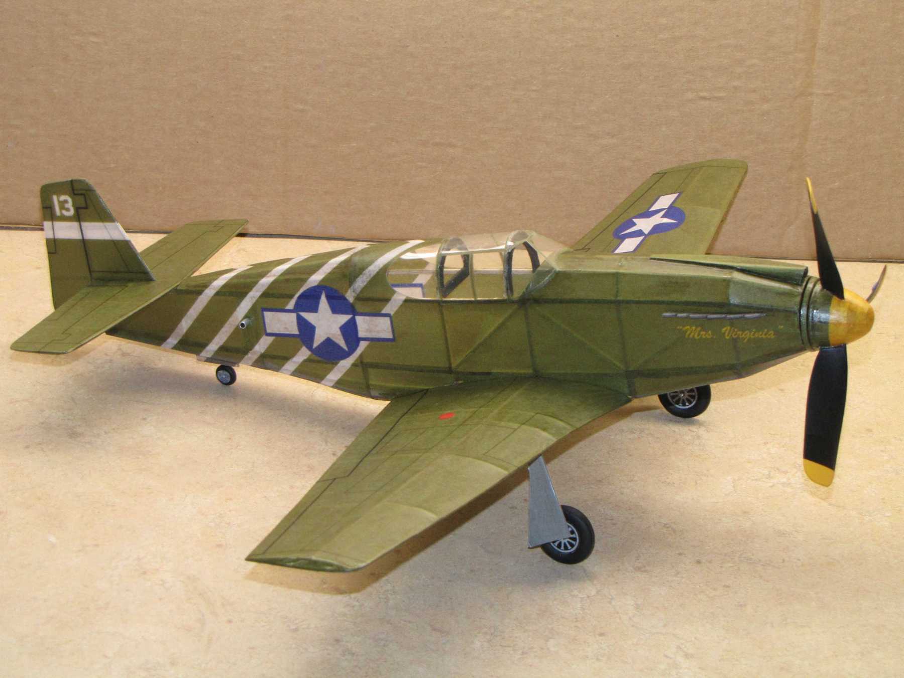
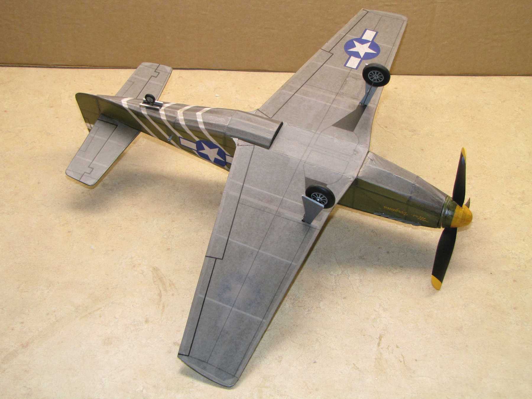
As a self teaching project for learning 3D CAD techniques I decided to use one of the Comet designs as a platform. Many of the original plans and corresponding part drawings can be found on the Internet. I located one of my personal favorites, the P-51A. That early model P-51 came after the North American Apache which was likely the actual airplane modeled by Comet. As presented, the Comet design has been tweaked just a bit so I'm calling it a P-51A. The images show a CAD 3D rendering of the model based on the developed plan, and the actual model built from the plan. The model is covered with tissue that has the color and markings applied with an ink jet printer. The tissue has two coats of nitrate clear dope that had been thinned with equal parts of thinner. The three bladed prop was made from two conventional plastic rubber props. A few minor changes have been made to the structural design. These are quite minor. Examples include addition of a fuselage former to make it easier to form the transition between the bottom air scoop and the rear fuselage, use of balsa plates where the wing attaches to the fuselage, and the landing gear arrangement. The nose former has also been adjusted to allow for a removable nose plug for stretch winding the motor. The CAD drawn plan package is here (1,549mb). Parts laid out for printing on letter size sheets of T-shirt transfer paper (74.3kb). The original plan and part set is here (1,931mb). The tissue layouts used for creating the printed tissue on this model can be found here. (19kb). The method I used for making the three bladed prop can be found here. |
 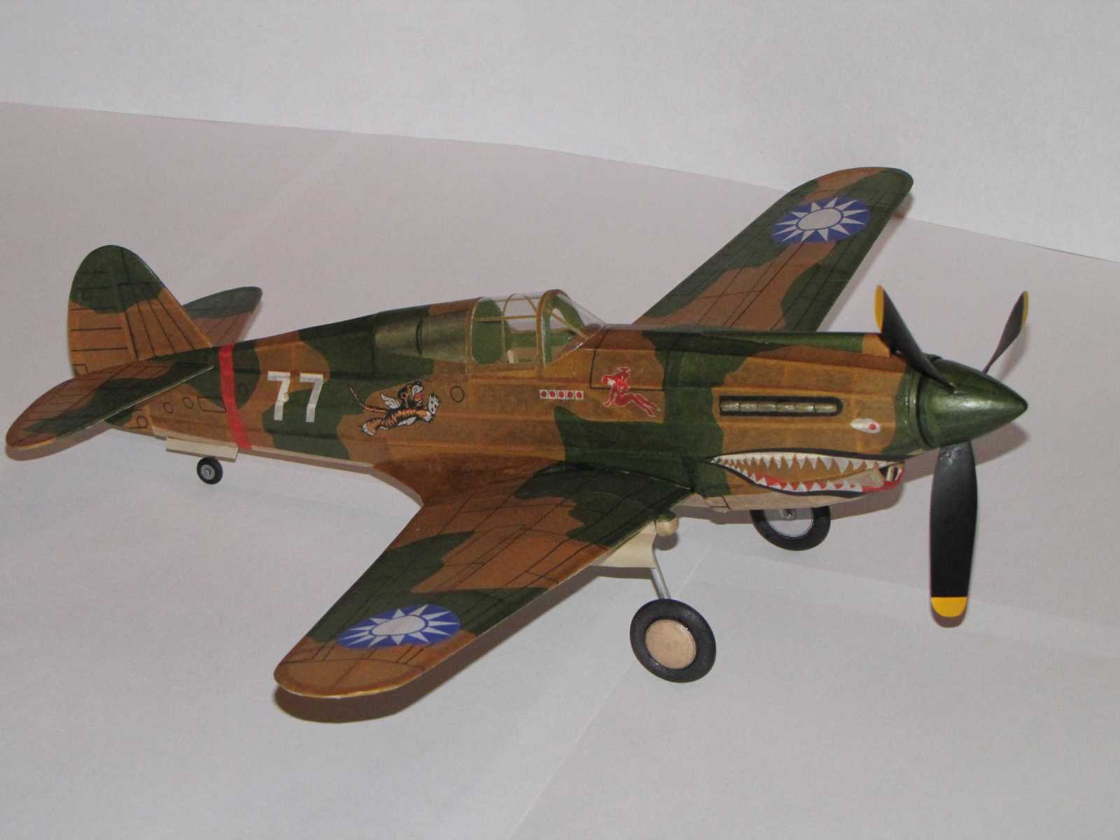 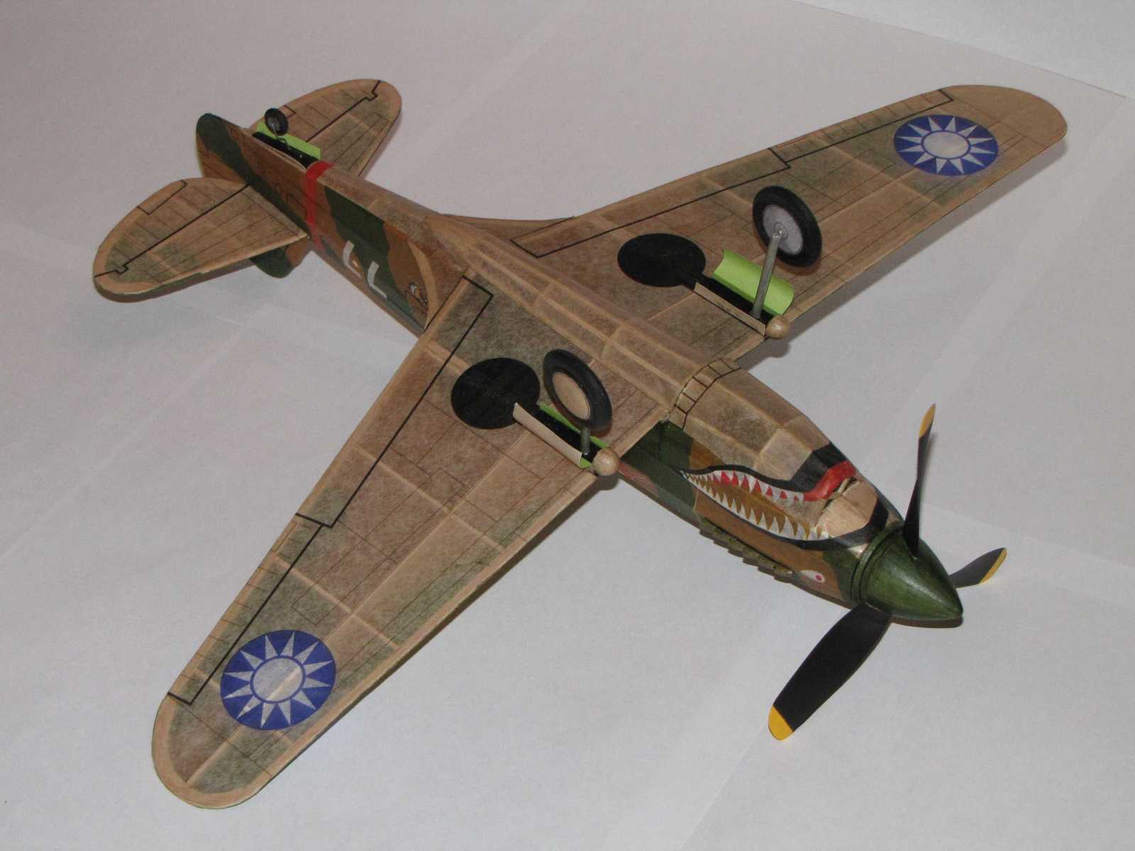 |
Comet 18"
P-40C. There were two versions. One used a built up box fuselage with
formers added. The other used the crutch and former method of fuselage
construction. The package being offered is the box based fuselage
design.
The images show a CAD 3D rendering of the model based on the developed plan, and the actual model built from the plan. The model is covered with tissue that has the color and markings applied with an ink jet printer. The tissue has two coats of nitrate clear dope that had been thinned with equal parts of thinner. The three bladed prop was made from two conventional plastic rubber props. A few minor changes have been made to the structural design. The 1/16" square top mounted wing spar has been replaced with a full depth 1/16" sheet balsa spar. A few diagonals have been added to the fuselage to improve torsional rigidity. The landing gear installation uses piano wire rather than dowels and pins. The nose side profile has been adjusted to be in better conformance to the full scale airplane profile. The nose former has also been adjusted to allow for a removable nose plug for stretch winding the motor. The CAD drawn plan package is here (645 kb). Parts laid out for printing on letter size sheets of T-shirt transfer paper (219.3kb). The original plan and part set is here (1,01kb). The tissue layouts used for creating the printed tissue on this model can be found here. (158kb) The method I used for making the three bladed prop can be found here. |
 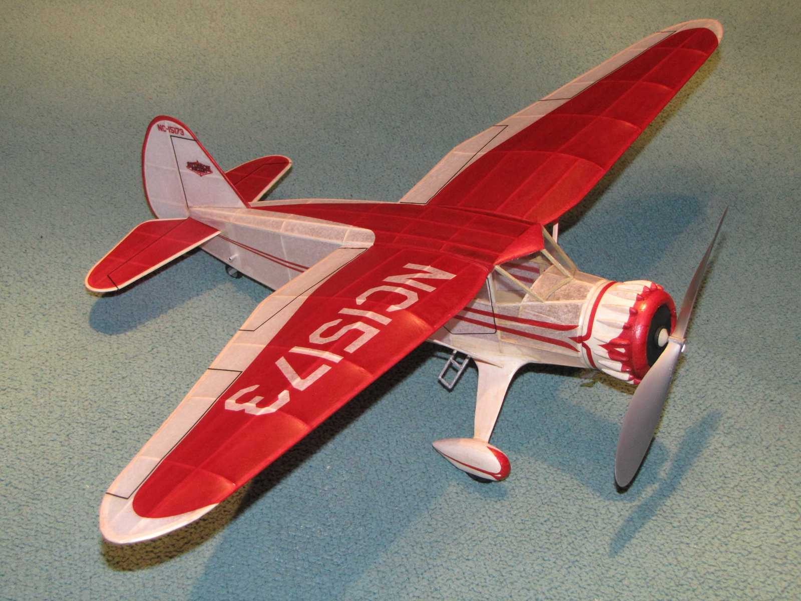 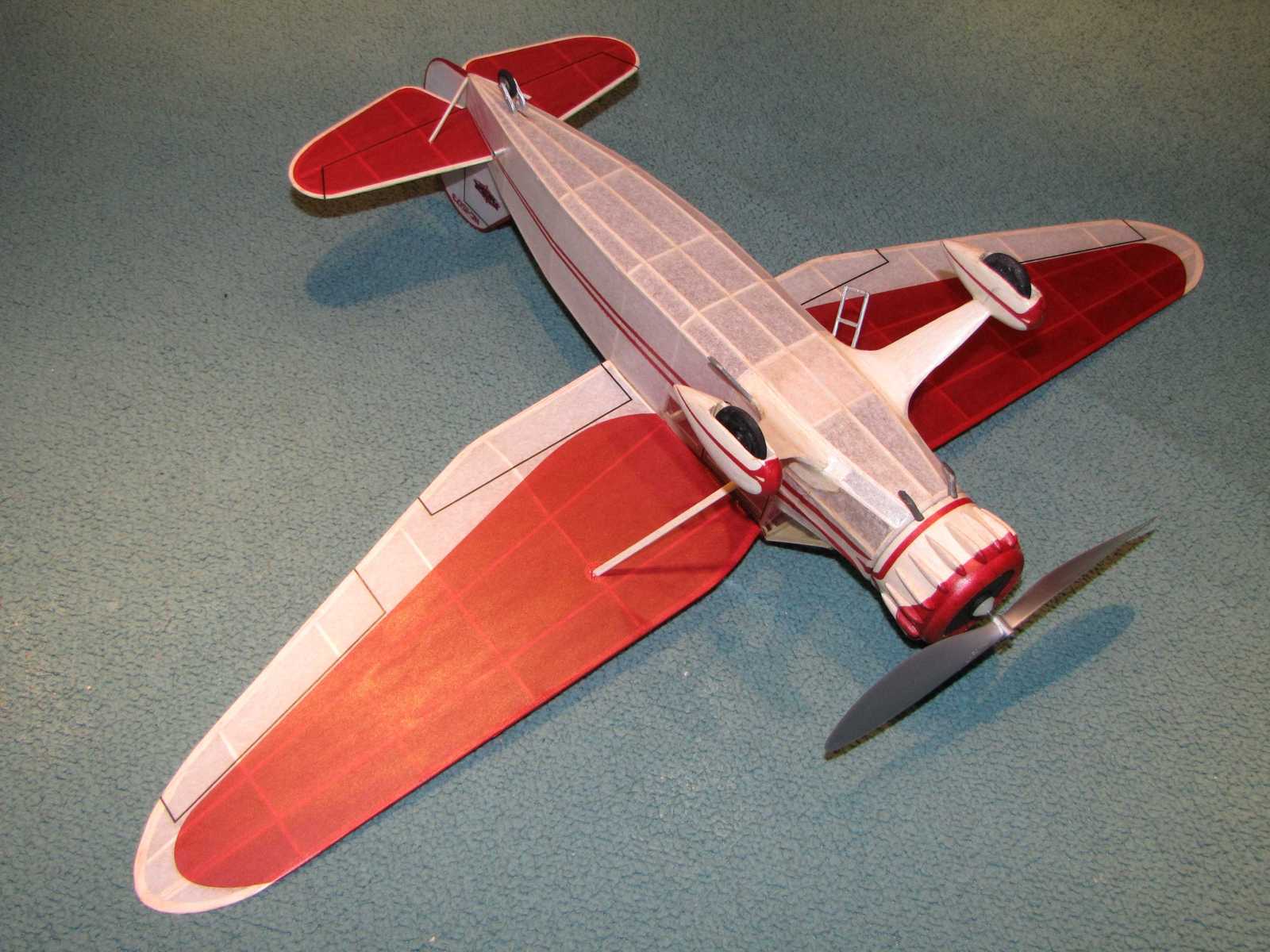 |
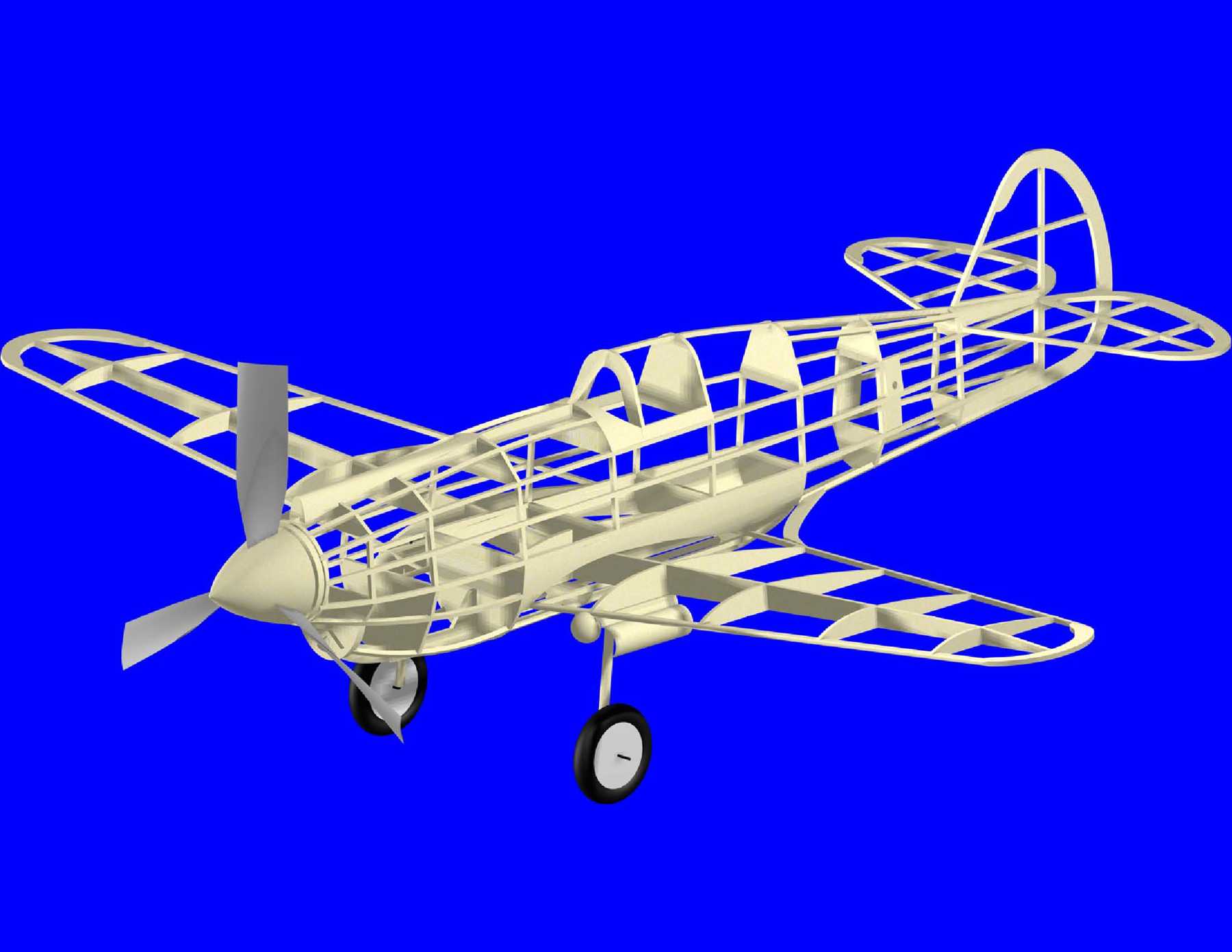
Comet 25" Stinson Reliant SR-7. The images show a
CAD 3D rendering of the model based on the developed plan, and the
actual model built from the plan. The model is covered with tissue that
has the color and markings applied with an ink jet printer. The tissue
has two coats of nitrate clear dope that had been thinned with equal
parts of thinner. As was done with the P-51A and P-40C, a few structural modifications were incorporated in the plan for the Stinson. These included addition of a top 1/16" square wing spar, addition of piano wire to the landing gear installation, addition of balsa sheet filler to the landing gear mount area, use of balsa for the cowl rather than paper, and a removable nose plug to allow stretch winding. One other change made was the license number shown on the original kit plan. A look up of that number shows it was actually issued to a Monocoupe. Reversing the last two digits corresponded to a Stinson SR-7. Photos were found of the actual airplane and the markings were taken from those photos for the model. The CAD drawn plan package is here (1.34mb). Parts laid out for printing on letter size sheets of T-shirt transfer paper (104kb). The original plan and part set is here (293kb). The tissue layouts used for creating the printed tissue on this model can be found here. (449kb) |
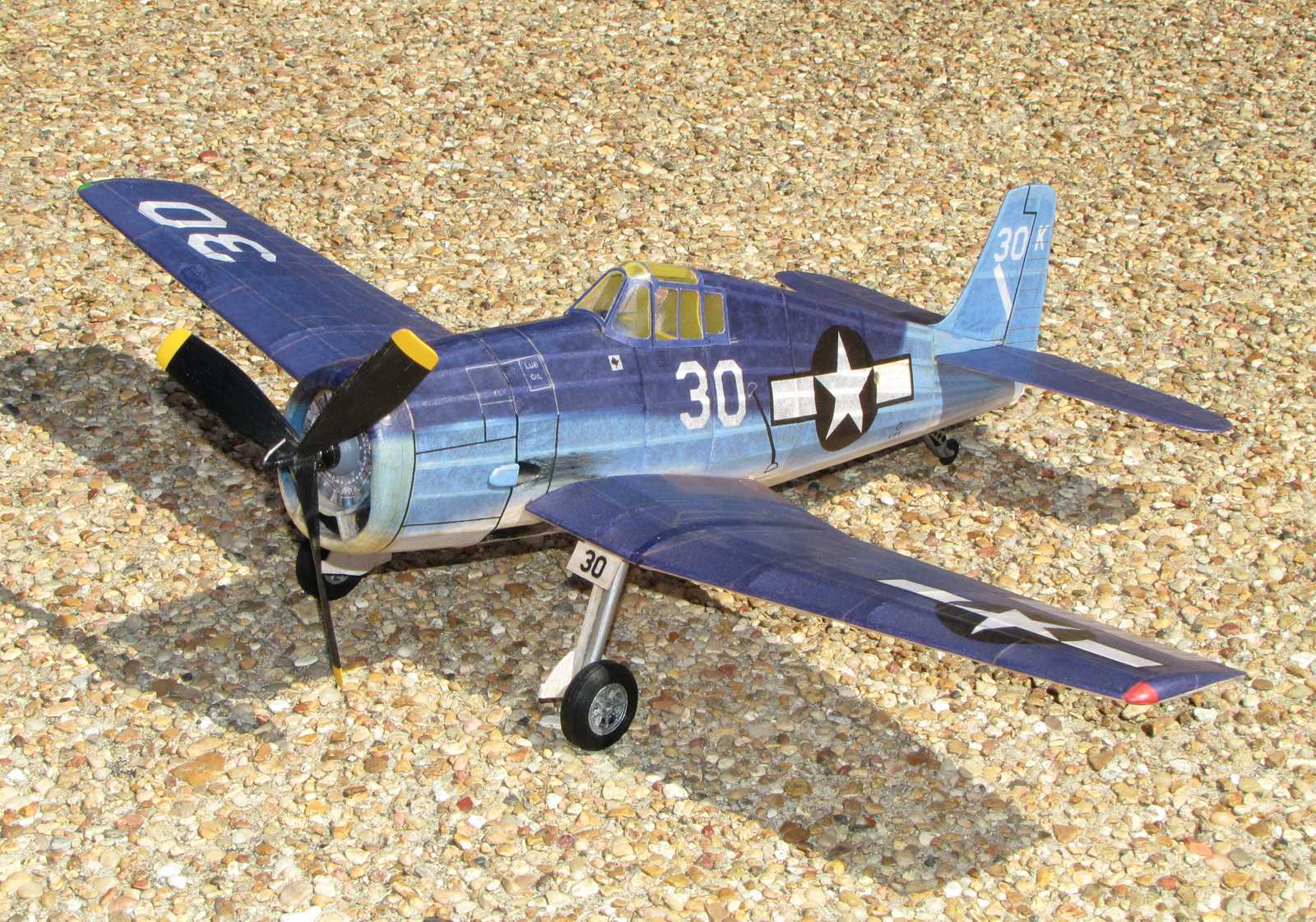 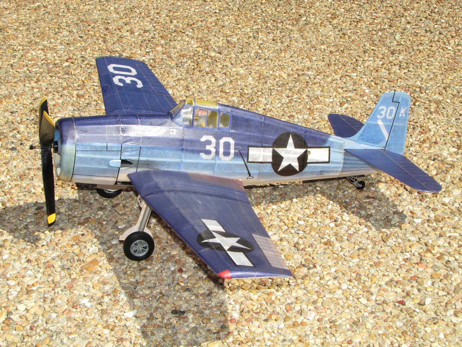 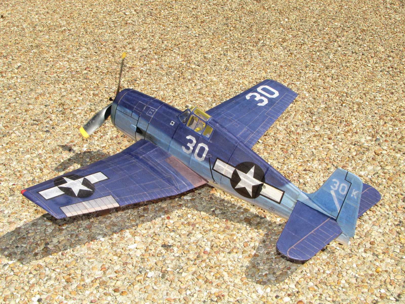 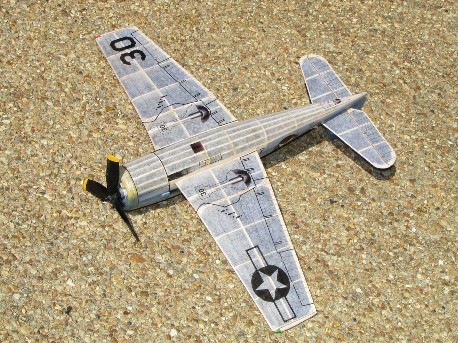 |
Comet 24" F6F-3 Hellcat. The model is covered with tissue that
has the color and markings applied with an ink jet printer. The tissue
has three coats of nitrate clear dope that had been thinned with equal
parts of thinner. The propeller, wheels, and removable nose plug were
created with a 3D printer. A few modifications were incorporated in the CAD drawn plan for the Hellcat. Examples are addition of top 1/16" square wing sub-spars, making the landing gear removable, addition of balsa block filler below the fin, a removable nose plug to allow stretch winding, and a few other minor changes. Markings are for a Hellcat that served in VF-1 on the USS Yorktown in the Marianas June 1944 (source: U.S. Navy Carrier Fighters Of World War II, Squadron/Signal Publications). Available for download is an illustrated assembly guide (938 kb), plan package that prints on US legal paper (8.5"x14") (364 kb), tissue printing layouts with the unit markings used for the model in the photos (276 kb), tissue layouts without any unit markings (281 kb), parts normal orientation (137 kb), parts mirrored for iron on transfer paper (183 kb), the 3D printer file for the propeller (9.4 mb), the 3D printer file for the wheels (46.2 mb), and the 3D printer file for the removable nose block set up for a Gizmo Geezer front end (2.2 mb). Note that the 3D printed 7.5" diameter propeller used for the model that is provided here has a hypotwist pitch distribution. The pitch to diameter (P/D) ratio from the hub out to the 75% radius point is 1.2. From the 75% radius point out to the tip the P/D increases linearly to 1.8. The use of hypotwist is based on a paper by Bruce Holbrook that is available on the National Free Flight Society web site in the Technical Library section. A set of laser cut parts for this model can be purchased from Aerowerkes.com. The parts package is in the SRK section under COM 3505PB. |